
DALI Lighting Control Guide: How to Select Drivers, Plan Wiring and Configure Different Projects
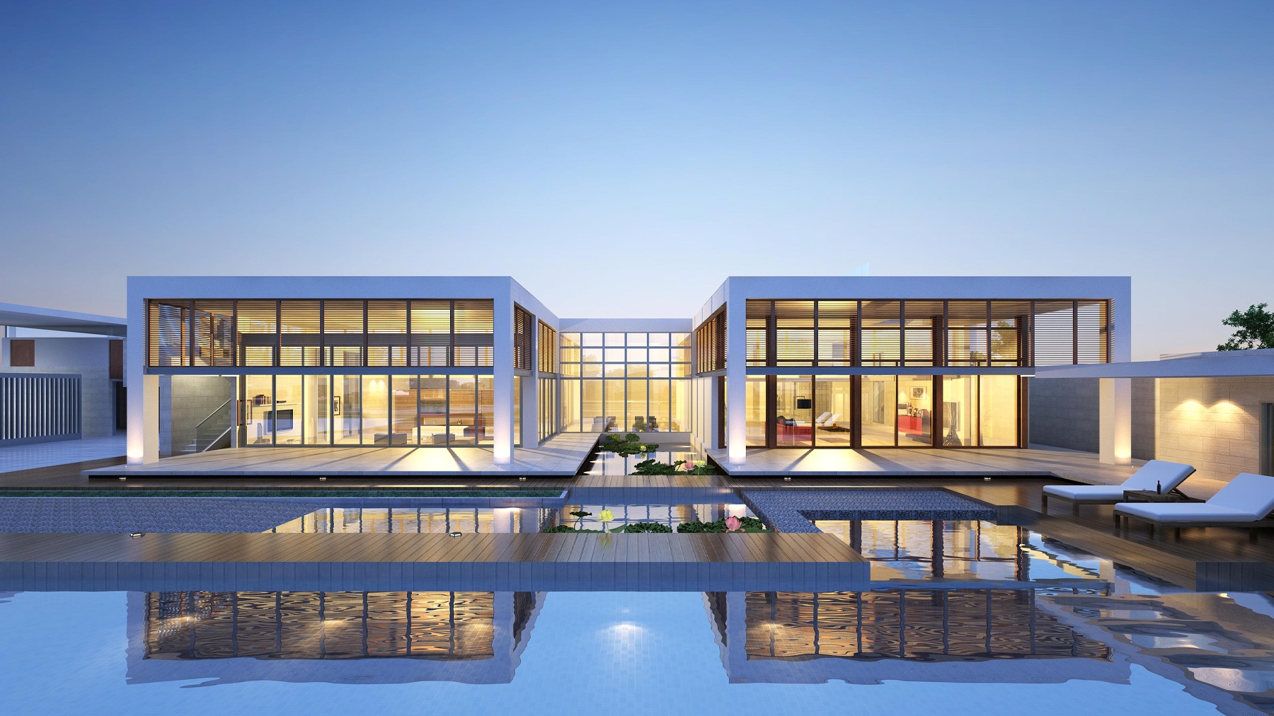
Modern lighting systems need to do more than switch lights on and off. Offices require responsive lighting for different work areas, hotels need flexible scenes for guest comfort, and villas often call for personalized control across multiple rooms and floors. DALI lighting control makes this possible through digital communication between compatible lighting devices.
However, a reliable DALI installation depends on more than choosing DALI-compatible products. Drivers, bus power supplies, control devices and wiring layouts must all be matched to the project's lighting requirements and physical structure.
This guide explains how to plan DALI lighting control for office, hotel and villa projects, with a focus on equipment selection, bus power calculation and practical wiring design.
1. DALI Lighting Control: The Essentials
DALI (Digital Addressable Lighting Interface) is a standardized digital lighting control protocol defined by the IEC 62386 series. It enables individual addressing, group control, scene recall and, where supported, two-way communication with connected devices.
Compared with basic 0–10V dimming, DALI is particularly useful when a project requires flexible lighting zones, software-based reconfiguration, sensor integration or device status feedback. DALI-2 also standardizes application controllers and input devices, supporting improved interoperability between certified products.
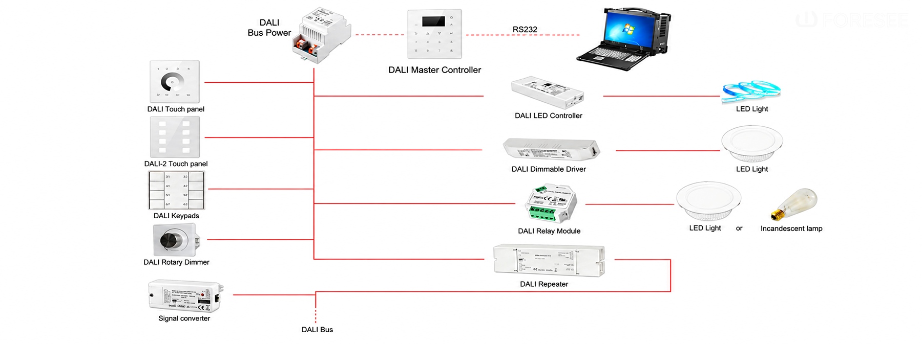
A typical DALI system includes:
- DALI LED Drivers: Regulate power to LED light sources and respond to dimming commands.
- Application Controllers: Process control logic and issue commands to lighting devices.
- Input Devices: Provide user or environmental information, such as wall switches, occupancy sensors and daylight sensors.
- DALI Bus Power Supply: Supplies power to the communication bus and bus-powered devices.
- Lighting Fixtures: Produce illumination according to the control settings.
The DALI bus carries both communication signals and bus power over the same two-wire connection. A DALI-2 subnet supports up to 64 control gear addresses and 64 control device addresses. These limits, together with bus current and cable distance, should be considered when dividing a project into lighting-control lines.
2. DALI System Selection and Configuration for Office Projects
Office lighting usually combines open-plan work areas, meeting rooms, private offices and circulation spaces. Each area has different lighting requirements, so the first step is to define lighting zones before selecting drivers and planning the DALI bus.
2.1 Divide Lighting into Functional Zones
In an open-plan office, luminaires can be grouped according to desk areas and their distance from windows. Daylight sensors can help adjust lighting near windows, while occupancy sensors can support automatic control in meeting rooms and shared spaces.
Meeting rooms may require separate control of general lighting, lighting above the conference table and presentation lighting. Private offices can use individual dimming controls, while corridors may use occupancy-based dimming.
This zoning plan determines how many drivers, input devices and control functions the system needs.
2.2 Select Drivers According to the Lighting Loads
For standard dimmable office luminaires, DALI DT6 drivers are commonly suitable. The correct driver must match the LED load:
- For constant-current LED modules, check the required output current and ensure the driver's voltage range covers the LED module's operating requirements.
- For constant-voltage LED strips, select a driver with the matching voltage, such as 12V or 24V DC, and sufficient output power.
- For tunable-white lighting, use compatible colour-control equipment, such as a DALI DT8 driver, when the required colour-temperature control is supported.
For example, a constant-current LED module rated at 700mA and operating at 36V has a nominal power of 25.2W. The selected driver should provide a regulated 700mA output, cover the module's actual voltage range and have an adequate power rating. The same principle applies when selecting drivers for office downlights, linear lights and other luminaires.
2.3 Calculate Bus Power and Plan the DALI Lines
After defining the devices in each zone, calculate the bus current required by the application controller, sensors, input devices and any other equipment drawing power from the DALI bus.
A standard DALI bus typically operates at approximately 16V DC. The combined guaranteed supply current of the bus power supplies on one subnet must be sufficient for the connected devices, while the total supply current must not exceed 250mA.
For a small office floor, one DALI subnet may be sufficient if the device count, bus current and cable distance remain within the limits. For a larger office with multiple floors or extensive lighting zones, separate subnets may be more practical. This also helps organize commissioning and future maintenance.
Illustrative planning example:
A single office floor has several open-plan lighting zones, two meeting rooms and a group of private offices. The design team first lists all DALI drivers and control devices, then checks their individual bus-current consumption against manufacturer datasheets. If the total bus load approaches the available supply capacity, or the address or cable-distance limit is reached, the floor can be divided into additional DALI subnets.
2.4 Plan Wiring Around the Office Layout
A line, star, tree or mixed topology can be selected according to the floor plan and equipment locations. For example, a main bus route can follow the office corridor, with branches extending to meeting rooms and work areas.
The bus must not form a closed loop. As a common design reference, 1.5mm² two-core cable is recommended, with a maximum distance of 300m between the two furthest devices under the specified conditions(ensuring the maximum voltage drop across the bus does not exceed 2V).
The final wiring plan should also account for cable routes, distribution points, voltage drop and access for maintenance. A well-planned layout makes it easier to locate devices, commission lighting groups and modify office zones later.
3. DALI System Selection and Configuration for Hotel Projects
Hotels combine private guest rooms with public areas such as lobbies, restaurants and corridors. These spaces have different operating patterns and lighting priorities. A practical DALI design should therefore separate room-level control from public-area lighting management.
3.1 Configure Guest Room Lighting by Function
A guest room may include downlights, bedside lights, decorative lighting and concealed LED strips. Rather than controlling all fixtures together, divide them into functional groups.
Typical scenes include:
- Welcome: Activates selected general and decorative lighting.
- Reading: Provides suitable light around the bed or reading area.
- Relax: Reduces general lighting and emphasizes softer ambient light.
- Night: Keeps selected low-level lighting active for movement.
For standard dimming, compatible DALI DT6 drivers can be used. If the room requires tunable-white control, select drivers that support the required DALI DT8 colour-control function. The driver must also match each luminaire's electrical characteristics, including constant-current or constant-voltage requirements.
Wall controls, bedside input devices and occupancy sensors can provide local control. Where guest-room management systems are involved, a suitable application controller or gateway is needed to connect the DALI lighting network with the wider hotel control system. DALI alone should not be assumed to directly manage door locks, HVAC or curtain motors.
3.2 Plan Public-Area Lighting Separately
In lobbies and restaurants, general lighting, decorative fixtures and accent lighting should be assigned to separate groups where independent control is required. This allows the hotel to create different lighting scenes for daytime operation, evening ambience, events and cleaning.
Corridors can be divided into floor or section-based zones. Occupancy sensors and scheduled control may be used where appropriate, depending on the hotel's operating requirements and safety strategy.
Driver selection should follow the actual fixture types. For example, decorative LED fixtures may require different output characteristics from constant-voltage cove lighting. Each driver must be checked against the connected LED load and the required dimming performance.
3.3 Size Bus Power and Divide Subnets by Floor or Function
A small hotel or boutique property may be able to organize its DALI network around a limited number of lighting areas. A larger hotel will generally need a more structured arrangement, with separate DALI subnets for guest-room floors, public areas or other functional zones.
For each subnet, calculate the bus-current consumption of all connected devices using their datasheets. Check the number of control gear and control device addresses, and ensure the combined bus power supply current does not exceed 250mA.
Do not assume that one bus power supply can serve an entire hotel. The required number of supplies and subnets depends on the actual device quantities, bus-current consumption, cable distances and control architecture.
3.4 Match Wiring Topology to the Building Layout
For guest-room floors, a main bus route along the electrical or service corridor may provide a practical starting point, with branches serving room groups. Public areas can be arranged on separate lines where this makes commissioning and operation easier.
Line, star, tree and mixed topologies are permitted, but closed-loop wiring must be avoided. Keep the distance between the furthest devices within the recommended limit and check the cable size and voltage-drop conditions.
Separating guest-room and public-area networks can also make fault isolation and maintenance more manageable, particularly in larger properties.
4. DALI System Selection and Configuration for Villa Projects
Villa lighting often involves more varied fixture types and more personalized control than a standard apartment. A single property may include living rooms, dining areas, bedrooms, stairways, corridors and outdoor spaces. The design should reflect both the lighting layers and the building's floor plan.
4.1 Select Drivers for Different Lighting Types
In a living room, downlights, cove lighting, decorative pendants and accent lights may need independent dimming. Bedrooms may combine general lighting, bedside lights and indirect lighting, while dining areas may require separate control of the dining pendant and surrounding ambient lights.
Driver selection depends on the light source:
- Use a compatible constant-current DALI driver for constant-current LED modules.
- Use a matching constant-voltage DALI driver or dimming interface for 12V or 24V LED strips, according to the system design.
- Use DALI DT8-compatible equipment when tunable-white or other supported colour-control functions are required.
For outdoor lighting, check the fixture and driver protection ratings and ensure they are suitable for the installation environment.
4.2 Create Lighting Groups and Personalized Scenes
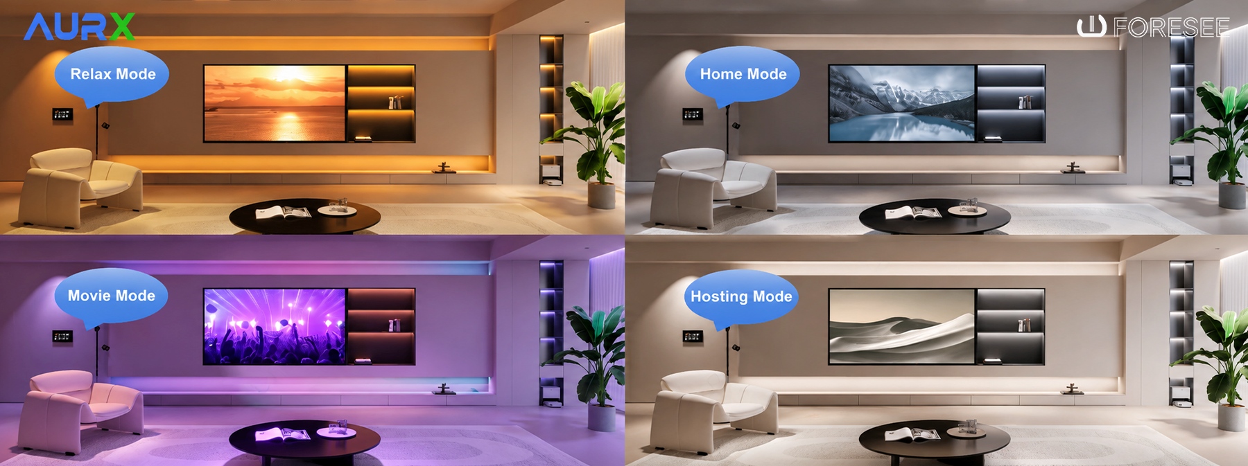
The control plan should follow how residents use each space. For example, a living room may have separate groups for downlights, cove lighting and decorative fixtures. These groups can be combined into scenes such as Entertaining, Movie and Relax.
A dining area can have separate control for the pendant and general lighting. Bedrooms may use Reading, Relax and Night scenes, while stairways and corridors can incorporate occupancy-based control where suitable.
The number and type of drivers should therefore be determined by the desired lighting groups and functions, not simply by the number of rooms.
4.3 Plan Bus Power and Wiring Across Multiple Floors
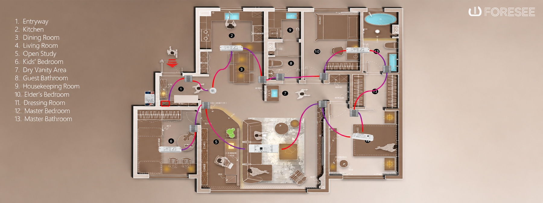
In a multi-floor villa, the DALI network can be divided by floor or functional area. For example, the ground floor may cover the living and dining areas, while the upper floor serves bedrooms and corridors. This arrangement can simplify cable routing and make system maintenance more manageable.
For each subnet, count the connected control gear and control devices, then calculate their total bus-current consumption from the manufacturers' specifications. Check the 64 control gear address and 64 control device address limits, as well as the 250mA maximum bus supply current.
A line or tree layout may suit a villa with a central distribution route, while a mixed topology can accommodate branches to different rooms. The bus must remain an open network rather than a closed loop. Cable distance and voltage drop should be checked across the complete route, including branches.
Where the villa uses a wider smart-home platform, a compatible gateway or system controller can connect DALI lighting with other automation functions. The required interface depends on the protocols and equipment used by the wider system.
5. Essential DALI Wiring and Installation Considerations
Although the wiring layout should be designed around each project, several technical requirements apply across DALI installations.
|
Item |
Design consideration |
|
Bus wiring |
Two-wire connection carrying both communication and bus power |
|
Polarity |
DALI bus wiring is polarity-independent |
|
Topology |
Line, star, tree and mixed arrangements are permitted; do not create a closed loop |
|
Cable reference |
1.5mm² two-core cable is a commonly recommended reference |
|
Cable distance |
Up to 300m between the furthest devices under specified conditions |
|
Bus voltage |
Typically approximately 16V DC |
|
Bus current |
Combined bus power supply current must not exceed 250mA per subnet |
|
Address capacity |
Up to 64 control gear addresses and 64 control device addresses per DALI-2 subnet |
The 300m distance is measured between the two furthest devices, not necessarily the total length of all cable branches. Actual installation conditions, cable characteristics and voltage drop must be checked during design.
Also distinguish between the DALI bus power supply and the LED driver's output power. The bus supply powers communication and bus-powered devices; the LED driver supplies the connected light source. They serve different purposes and must be sized separately.
After installation, commissioning should include bus voltage and power checks, device discovery, short-address assignment, group configuration, scene programming and individual dimming tests. Verify that all devices respond correctly before handing over the system.
6. Build Smarter Lighting Systems with 4C Global
A reliable DALI lighting project starts with a clear understanding of the space, the connected lighting loads and the required control functions. Driver selection, bus power calculation, device addressing and wiring design should be considered together to create a system that is practical to install, commission and maintain.
As a leading smart building solutions provider in China, 4C Global focuses on intelligent building technologies and connected control solutions for residential and commercial environments.
Explore the 4C Global Smart Home to discover our product range, or contact our team to discuss your project requirements and identify suitable lighting control solutions.
4C Global – Connecting Technologies, Creating Smarter Spaces.